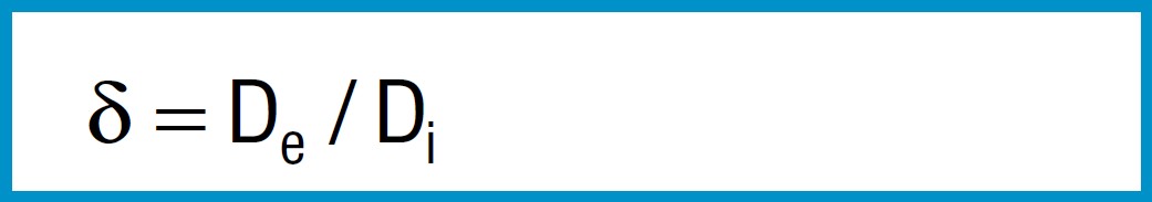
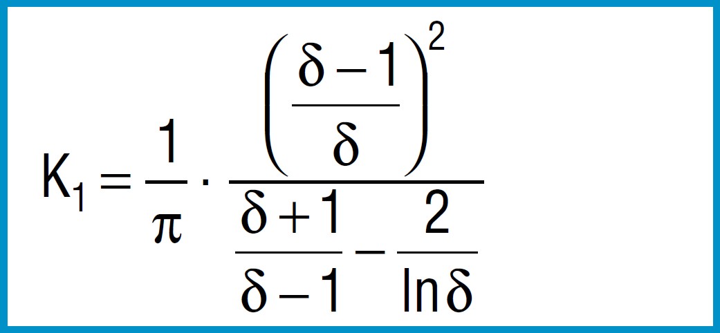
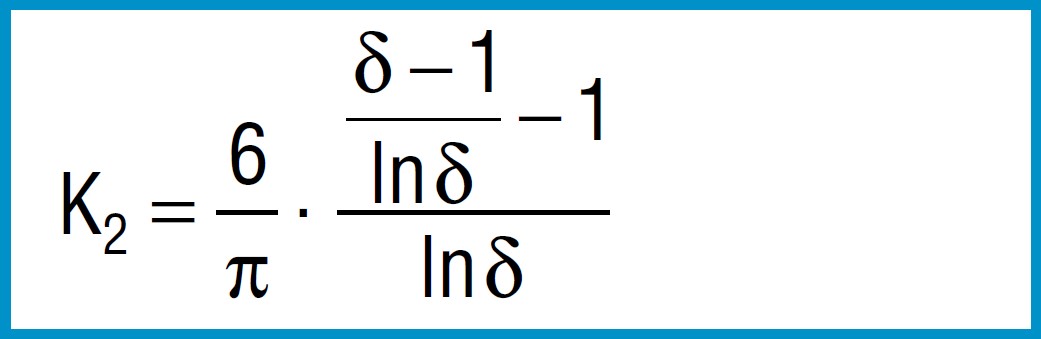
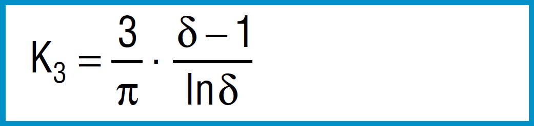
equations for calculation
These are valid for all disc springs.
Characteristics
Formula 2
Formula 3
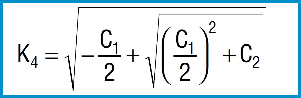
Formula 4
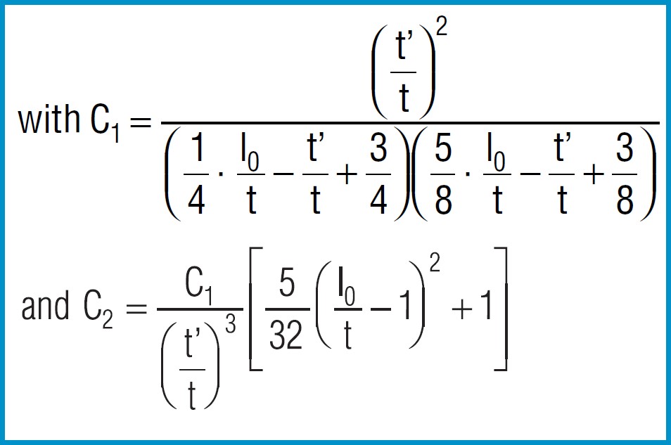
Formula 5
Formula 6
Spring Force
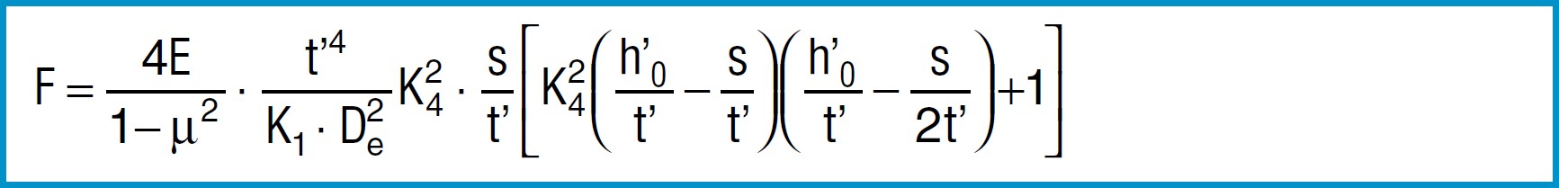
Formula 7
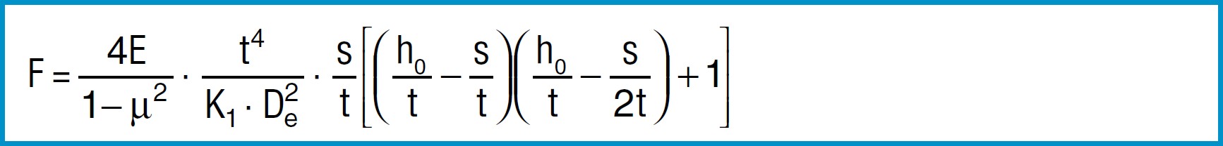
For disc springs manufactured to group 1 and 2 K4 = 1:
Formula 8a
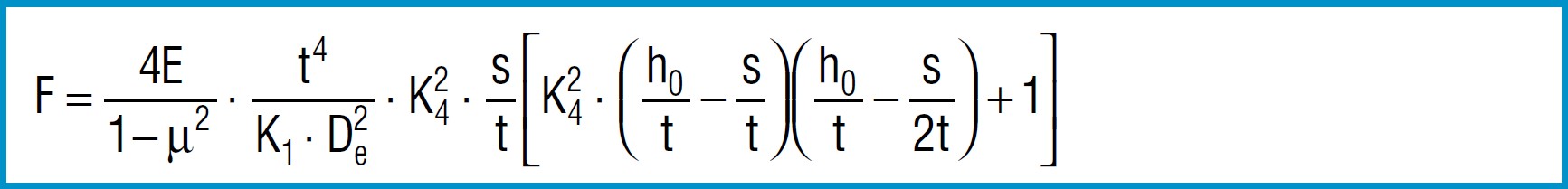
For disc springs manufactured to group 3 with contact flats and reduced thickness, t’ and ho’ must be used
(ho’=lo-t’):
Formula 8b
Young’s modulus ‘E’ is virtually independent of the heat treatment condition and tensile strength of the material.
For steel springs with dimensions in accordance with DIN 2093, formula 7 provides values which correspond closely to the measured values.
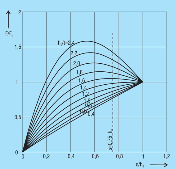
The force of a disc spring does not increase linearly with the deflection, but is always regressively curved. Its pitch, i.e. the rate, decreases with increasing stroke. The ratio of curvature is determined exclusively by the ratio ho/t, as can be seen in figure 3.
Figure 3 - click to enlarge
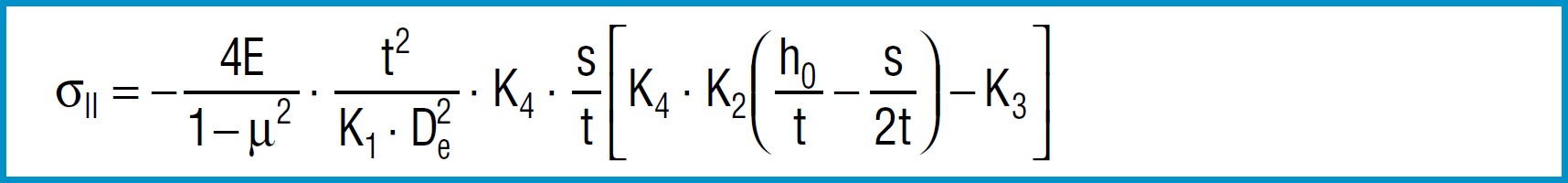
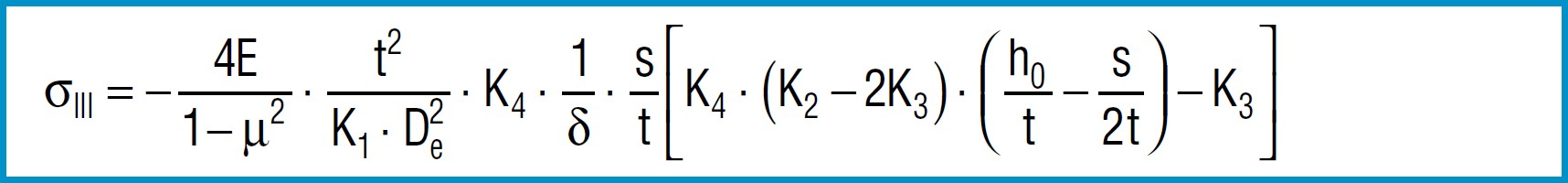
Stress Calculations
Formula 9
Formula 10
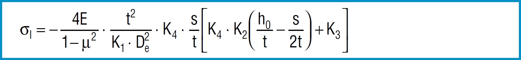
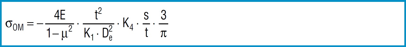
Formula 11
Formula 12
Formula 13
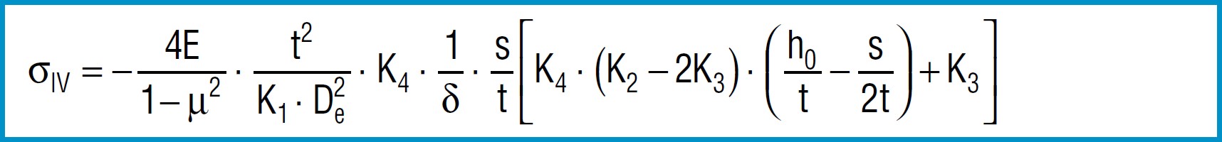
Here
4E = 905 495 N / mm2
1 - µ2
also applies to spring steel. Positive values are tensile stress and negative values are compressive stress. It is important to remember that this the calculated stress is a normal value and that the actual stress is considerably lower, as it is considerably influences by the ever-present internal stress.
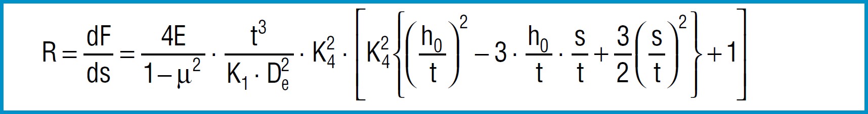
Spring Rate
Through differentiation of the spring load F in accordance with the reflection s, the following formula is obtained for spring rate R:
Formula 14
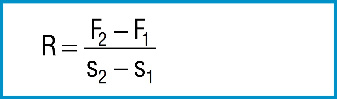
The spring rate between any two adjacent points F1, s1 an F2, s2 can be approximated by means of the following simple formula:
Formula 15
Spring Work
The work done by a disc spring can be obtained by integrating formula 7 for the load F according to the deflections:
Formula 16
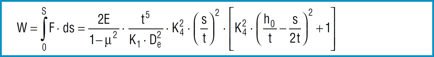
For a limited area of application it can be integrated between the two deflections s1 and s2.